COR55 & COR60 R.A.V.

Reliability Adaptability Versality

COR55/60 RAV It is an interesting alternative to traditional Trawler Yachts with a full raised Pilot House.
When designing this yacht, we tried to combine all the previously known solutions to create a nice and fresh silhouette.

Because COR55/60 is definitely a travel and family yacht. The design priority was broadly understood functionality. Decks, interior, mechanical, systems.

The hull of this yacht is a stable, semi-displacement shape. Provides excellent stability and efficiency at speeds of 7-10kts. At any time, allowing you to develop higher cruising speeds.


All systems and mechanical systems have been designed to be as simple as possible and easy to repair. components readily available around the world. Repair scopes can be easily performed directly by the owner-operator.

SEMI CUSTOM PRODUCTION.
The customer has a very large influence on the interior, finish, selection of systems, mechanical systems and tank capacity.
The construction program assumes that the ordering party will be involved in the construction process if he or she so desires.

The yacht is available in two general lengths: 55ft and 60ft.
It can be ordered without Flybridge. The scope of personalization is very wide and is limited to the hull geometry.

We have provided more information about the COR55/60 RAV in the Specification tabs.

COR55 RAV

COR60 RAV

TWO LENGTHS OF HULL


Main particulars COR55/60 RAV PILOT HOUSE

PROPERTIES [m] [ft]
LOA Length with short swimming platform 55/60 17,9/18.9 59 / 62
BOA Beam overall 5,425 17,79
LWL Loaded waterline length 55/60 17,2/18,2 56.5/59,5
T draft 1,85 6.1
DA draft air 8,4 27,6
D(T) Loaded displacment 56,5 t 100.060 lbs
CE APPROVAL CATEGORY A Ocean
Crew limit 14
Hull type Semi-displacment with ETE (Extended Trailing Edge)
Hull Meterial GRP
Superstucuters / Deck GRP
Accomodation 8+3
Sleeping places up tp 11
Enigne Horse Power form 2x230 up to 2x425
Speed 5-15kts
Averange range at 7kts approx. up tp 4000 NM 15%reserv

The project team

POSITION NAME
Naval architect Grzegorz Władziński
Analysis CFD and improv. Grzegorz Władziński
Conception designer CY Damian Dymecki
Exterior designer Cormorant Yachts Team
Interior designer Cormorant Yachts Team
Construction designer STRUCTeam LTD UK
Builder Cormornat Yachts Shipyard Gdańsk

Tank capacity

PROPERTIES [L] [GAL]
Diesel total 8700 2298
Potable water tank 400 92,47
Fresh water tank 1800 501
Gray water tank 600 158,52
Black water tank 600 158,52
RINA

The RINA classification society supervises the construction of each of our yachts

Fuel consumption & Range charts

Dimensions

Layout SETS

COR55/60 R.A.V. Price & Specification

SAFETY FIRST

CONSTRUCTION

SEAWORTHINESS

ELECTRICITY AUTOMATION

NAVIGATION COMMUNICATION

DESIGN

INTERIOR PLAN

FUEL & RANGE

HVAC SYSTEM

PROPULSION STEERING


SAFETY FIRST

All design attention was focused on travel and the yacht’s ease of maintenance.

A large number of storage compartments provide freedom to store everything you need during cruises.
The on-board equipment has been designed to be simple, effective and, when necessary, easy to repair.

The aftdeck with the right half-deck can be completely closed, and an additional hatch will isolate this space during a cruise in a cold climate and when the yacht is in port.

As has a huge FLY DECK with increased load-bearing capacity.
This provides the ability to load large dinghies.
The natural balance has been organized so that the weights on the FLYDECK do not change the trim of the yacht.

The stern platform can be made enlarged and can be lowered into the water.

In the COR60 RAV version, the Aftedck is large and allows you to accommodate a large table.

CONSTRUCTION

Thanks to the excellent experience of the Structeam design office from Great Britain, the structure was designed in a very thoughtful way. In addition to the massive and heavy hull structure, multi-point connection nodes were used.

The yacht is made of GRP.
The first 4 layers are made wet with vinylester resin, and fabrics and fiberglass mats are abundantly soaked.

The remaining layers are made using the polyester resin infusion method

The floor of the lower deck forms an intermediate structure together with the system of supporting frames.
The hull at the bottom is very heavy, which helps to lower the center of gravity.
All critical parts of the hull are made of SOLID.

The upper areas, such as the superstructure, are permanently laminated. However, their weight is lower.
Structural grid under the flydeck. Consisting of numerous connections, it is very extensive and provides very good support for future loads from the RIB, additional tanks and equipment located on the FLY DECK.
Hartop is a lightweight laminate construction.

We use the highest quality structural adhesives to connect the elements and laminate all connections with at least 4000GR.

We use components from companies for construction
AOC – Switzerland
BUFA – Germany
Scott Bader – UK
DIPEX/SAERTEX – glass fabrics

Glazing
CE compliant – A ocean + 20% surplus.
Pasted and grouted glass
Tempered laminated glass with a total thickness of 10 to 16 mm depending on the installation zone.
Storm-coated windows in steel frames are possible


SEAWORTHINESS & BUOYANCY

All the hulls we use have been designed directly for us by the office of engineer Grzegorz Władziński. In response to the high demands, hulls were created that combine the following features.

  • Sharp bow on the waterline, squat where space is needed inside.
  • The almost vertical bow not only introduces a professional character to the silhouette. It allows you to make better use of the space in the interior. A large usable space is created between the bow edge and the collision bulkhead.
  • A high bow (over 3m / 10ft from the waterline) reduces soaking of the fore deck.
  • Reduced resistance in the speed range of 7-10kts.
  • The flattened stern allows a lot of carry when you need to go faster, such as when you want to get away from bad weather or reach anchorage before nighttime.
  • The flattened hull at the stern, devoid of the classic V, effectively reduces side-to-side swaying.
  • Wide on the waterline. Effectively contributes to increasing stability.
  • All weights have been placed as low as possible. The drive engines are placed extremely low. It is also conducive to lowering the rocking arm. Increases comfort on board.
  • The additional optional keel performs several functions. It adds buoyancy, allows you to add ballast, lower the center of gravity and increase the strength of the righting arm. Perfectly improves stability and prevents the hull from swinging. It protects the rudders and the screws at the sandbar passes, while the steel fittings of the trousers are secured by the laminate.
  • The cutting beak of the pear is not a typical bulbous beak. It definitely does a different job in our hulls. The cutting bow pear perfectly cuts the water in front of the hull proper, causing the water to stick to the hull and hold it as far as possible to avoid creating energy-consuming vortices. In addition, the modeling of its bottom part perfectly affects the comfort of swimming in the undulating sea.
  • On request, a stabilization system, active fins is available.
  • Our bow thruster tunnels are always designed and then CFD tested. We do it because basic modeling is not enough to contain the water in the vicinity of the bow rudders. As a result of these actions, we know that the water will not flow into the tunnel creating undesirable vortices and resistance.
  • We design the exits of our underwater exhausts using the same method.
  • The drainage of decks during stormy weather is ensured by storm drains. We always design them and then test their effectiveness. Our drains have a reverse blocking function.

Sharp bow on the waterline, squat where space is needed inside

Bow thruster tunnel with properly designed fairing and deflector

BULBOUS CUTTIN BOW For better comfort on a rough sea. For better fuel economy

We do not use traditional pressure bulbous bows as they are only suitable for one speed. Instead, we use a more useful solution. Cutting bow that increases efficiency with speed.

Without additional cutting bow

With additional cutting bow

In COR55/60 RAV Stabilization systems.

1.SLEIPNER Hydraulically driven 1.05sqm | 11.3sqft
2.SLEIPNER Electrically driven 1.1sqm | 11.8sqft
3.Passive anti-roll keels

In the case of a hydraulic system, it is combined with hydraulically driven thrusters.
There is no need to run the generator for the system to operate during the cruise.

CONTROL AND AUTOMATION SYSTEM

EMPIRBUS

Each CORMORANT has a hard-wire automation system. It is a panel with aesthetic buttons and controls. Its operation is the simplest possible. Starting a given system is done by pressing a button – and that’s it.
This solution allows the vast majority of devices to be connected with ordinary contactors. When the need arises, everyone will make repairs.
Moreover, for monitoring drive systems and generators. We assemble a Empirbus automation system. It is the highest possible quality electronic system made in Europe.
The system is expanded depending on the selected other equipment components.
The Empirbus system watches over all the yacht’s systems and displays them on its own screen or as a page on the MFD.
The levels in the tanks are also displayed in this system.
The system allows for enormous expansion possibilities according to customer wishes


Switch cabinets

  • Each cormorant has two main switchboards.
  • First It is located in front of the Engine room. It includes the main circuits of inverters, chargers and edge socket protections.
  • Second It is located in the Pilot House, it handles the selection of power sources, selection of power from edge sockets. 
  • Switching redundant systems. 
  • Supply bag for bilge pumps.
  • Switching battery banks
  • Charging source selection
  • The settings are made by means of simple rotary switches on the graphic table corresponding to the power supply system.
  • Everything has been planned in such a way that, in stressful situations, you have no doubts about what we do.

ELECTRICITY SYSTEMS

First of all, it should be noted that regardless of the adopted configuration, solutions and materials are of the highest quality to ensure the highest level of safety and many years of trouble-free operation

ELECTRICAL SYSTEM
Each of the CORMORANTS 55/60RAV could be build with two different type of power systems. Depending on the needs and expectations of users.

LEVEL 1 – this is the range of devices without redundancy, corresponding to the coastal rib. Built on the basis of one KOHLER 12kW current generator. Large 6400W 24VDC / 230VAC Inverter and 500Ah Battery Bank common to all on-board devices.
One shore connection socket at the stern.
Starting aid for CYRIX engines / generators

LEVEL 2 – is a range of devices dedicated to units in the LRC configuration, and for those who expect higher comfort / security.
The scope has redundant systems. Split port and starboard layout. Switchable.
Two power generators (18kW large and 12kW small) associated for parallel operation, able to synchronize their work. This configuration allows the large generator to be turned off at night and only a small one will turn on when needed.
Two 6400W 24VDC / 230VAC inverters work in this system.
Two large 720Ah battery banks each
Two additional alternators mounted on 175A engines each
Two isolation transformers for shore power protection.
Starting aid for CYRIX engines / generators
Generators can be increased on customer’s request in each system.
You can change the type of batteries in each system. from AGM to LiFePO4 (Lithium Iron Phosphate Battery)
In each system, upon the customer’s request, other sockets, switches and power architecture can be used.
Each power supply system is easy to use and the switchboards are intuitive.
Each power supply system has a separate battery bank to maintain the radio function and a single plotter with a GPS antenna for several dozen hours in the event of a total failure.
This bank is located above the main deck.
Each CORMORANT 55/60RAV has six large earthing plates located in such a way that the loads are always discharged.

MFD NAVIGATION & COMMUNICATION

Basic navigation solutions are divided into two levels.
The basic system is GARMIN LEVEL 1

In addition to excellent shipyard and user support from GARMIN.
Upon special request, it is possible to install FURUNO systems

NAVIGATION LEVEL 1

MULTIFUNCTION DISPLAY & NAVIGATION
GPSMAP MFD 16″ 2pcs in the Pilot House
GPSMAP MFD 16″ 2pcs  on the Fly bridge
GPS ANTENNA 24XD
PRIMARY AUTOPILOT REACTOR 40
SENSORS SAIL PACK 52 GNX (wind speed, wind direction, outside temp, water temp.)
RADAR GMR FANTOM 18

Communication:
Primary VHF – VHF 215i Pilot House + Full function handset on the Flybridge

NAVIGATION LEVEL 2
MULTIFUNCTION DISPLAY & NAVIGATION
GPSMAP  MFD 22″ 3pcs  in the Pilot House
GPSMAP  MFD 16″ 2pcs  in the Fly bridge

GPS ANTENNA 24XD
PRIMARY AUTOPILOT REACTOR 40
SENSORS SAIL PACK 52 GNX (wind speed, wind direction, outside temp, water temp.)
RADAR GMR FANTOM 18
RADAR GMR 1226 xHD2 open array antenna
CAMERA IP GC 200 in the engine Room
CAMERA IP GC 200 view stern direction

Communication:
LRC Transceiver package based on ICOM include:
Primary Radio Station VHF – Icom M605EURO Output Power: 1W/25W in the Pilot House + Flybridge stand alone panel
Secondary Radio Station VHF – Icom M605EURO Output Power: 1W/25W in the Pilot House + Flybridge stand alone panel
Icom M605Euro –  Third stations  Total Thee (3):
1.Engine Room Icom COMMANDMIC HM-229B + cables OPC-2384, 2.Crew Cabin, 3. Master Cabin
Radio Station HF/MF SSB – Icom M803 SSB Output Power:150W Frequencies 0.5-29.99Mhz
Radio Station SSB – The AT-140 automatic antenna tuner from ICOM M803 [is suitable for 1.6 to 30 MHz. Ideal for whip antennas, backstays etc. For 100 watts continuous power or 150 watts PEP]
Transponder AIS 800 TRANSCEIVER CLASS B
Antena GA™ 38 GPS/GLONASS
SATELLITE COMPASS MSC 10
inReach Mini Marine Bundle – Iridium satellite communicator

LEVEL 2 antennas package included:
One VHF Shakespeare 5230 Galaxy
One VHF Shakespeare 5309-R Galaxy VHF 23’ (7m) VHF Marine Band 9dB
One HF/MF Shakespeare 5310-R Galaxy SSB 23’ (7m) Full-Length Conductors
One AIS – Shakespeare 5225-XT-AIS Galaxy AIS/VHF Antenna 8′ (2.4m)  6dB Gain
One HDTV Shakespeare 3019 SeaWatch®  Seawatch ® Marine TV Antenna (19″ Diameter)
One Shakespeare 5235-XT Galaxy AM/FM Antenna 8’ (2.4m) AM/FM Entertainment Band
One Shakespeare 5239 Galaxy 9.25″(0.23m) World Band Cellular Antenna
One Shakespeare – WiFi receiver in Marinas 5248 Galaxy Wi-Fi Antenna 24″(61cm) Gain:8dB
finished in superstructure colour

At the customer’s request, a second autopilot system with a KOBELT pump is installed

Thermal camera is also available on request in level 1.
There are a number of options for extending the navigation systems at the customer’s request.


DESIGN

All design attention was focused on travel and the yacht’s ease of maintenance.

A large number of storage compartments provide freedom to store everything you need during cruises.
The on-board equipment has been designed to be simple, effective and, when necessary, easy to repair.

The aftdeck with the right half-deck can be completely closed, and an additional hatch will isolate this space during a cruise in a cold climate and when the yacht is in port.

Jak has a huge FLY DECK with increased load-bearing capacity.
This provides the ability to load large dinghies.
The natural balance has been organized so that the weights on the FLYDECK do not change the trim of the yacht.

The stern platform can be made enlarged and can be lowered into the water.

In the COR60 RAV version, the Aftedck is large and allows you to accommodate a large table.

RANGE AND FUEL SYSTEMS

The COR55/60 RAV has a gravity fuel system with a day tank, fed from side tanks located in the Engine Room and tanks located in the bow/midship compartment.

Tank capacities according to customer specifications and needs.

The fuel system is equipped with a fuel distributor with a double fuel transfer pump, a fuel centrifugation and polishing system, and additional double filters for engines with a switching function.

The tanks have pollution traps and easily accessible drainage.
The day tank has space for sediment and water to accumulate, which does not provide fuel for engines and generators.
The tanks are made of 4 mm thick stainless steel, in accordance with ISO standards, with additional reinforcements.
Points outside the engine room are made of durable composites.
Tank filling points are located on the starboard side

Additionally, a fuel tank with a pump for refueling the dingy can be located on the FLY DECK.

Below we present charts based on which you can get an idea of the fuel consumption and range of the COR55/60. Please note that these values apply to yachts with standard equipment. additional tons in the form of optional equipment or the amount of fuel in additional tanks will affect the power requirement and, therefore, reduce the range.

HVAC SYSTEMS

First of all, it should be noted that regardless of the adopted configuration, solutions and materials are of the highest quality to ensure the highest level of safety and many years of trouble-free operation

BILGE WATER

See description in the SAFETY FIRST tab

PLUMBING INSTALLATIONS

  • COR55/60 It has a large space located right next to the keel for transporting media.
    The configuration of fresh water, gray water, black water depends on the customer’s needs.
    A typical configuration is:
    Fresh water – 1800L
    Gray water – 600L
    Black water – 600L

    The pipe installation is made of dedicated rubber hoses.
    Anti-odor in black water installations.
    Pressure installations are made in the VIEGA-Germany system

Fresh water distribution.

  • CORMORANT COR55/60 RAV could be a double hydrophore system ensuring pressure during the highest load with the greatest amount of board guest.
  • The hot water tank could be a capacity of 100L. It has electric heaters 3kW / 230V.
  • In addition, the hot water tank is supplied with heat from the engines.
  • On request, a 60L / 16Usgal hot water tank is installed only for the Master cabin.

Gray water, toilets and waste water management

  • Gray water has drainage chambers with easy access for cleaning. It is always pumped into the gray water tank.
  • CORMORANT COR55/60 RAV is equipped with Tecma toilets with 230V high-capacity macerators
  • The toilets are flushed with fresh water. The control panel is dual-function with an indicator that the tank is full to 3/4 of its capacity.
  • Emptying of sewage tanks.
  • The solution for emptying the tanks is divided in two ways.

Emptying in the port. Could be pumping out the black water tank. While gray water is pumped into the black water tank. This solution helps to clean the black water tank. In addition, next to the sewage suction point, there is a rinsing valve, through which we can supply fresh port water, for cleaning the tank. The valves are located at the PilotHouse in degrees on the half deck starboard

Emptying in the sea. When the rules and common sense allow it. The gray water tanks are emptied directly into the sea using a sewage pump. The same has been solved for emptying black water.

  • The configuration of pumps and valves allows you to empty the tanks with only one efficient pump, switching the valves manually, thus changing the fluid circuits.
  • The black water pump and the gray water pump are of the same type, which allows them to be used interchangeably in the event of a failure.
  • In LRC configurations, an additional hand pump is installed for both Gray and Black water.
  • There are dense partitions in each of the tanks to prevent overflow of liquids. Each tank is equipped with an inspection with open access.
  • Each tank has an ultrasonic liquid level sensor with tank shape compensation. This means that the indicator on the control panel always shows the actual filling percentage instead of the sensor level.

DECK WASHING SYSTEM & ANCHOR WASHING SYSTEM

  • At the customer’s request, a fresh water deck washing system is installed. Quick-disconnect points for connecting a flexible hose are mounted in six places.
  • Washing of the anchor and chain is installed on request and can be done with fresh water or pressurized salt water.

AIR CONDITION

  • CORMORANT COR55/60 RAV has a cooling and basic heating system.
  • The cooling system allows you to limit the compressor capacity at night.
  • The LEVEL 2 electrical systems are designed to operate the air conditioning throughout the night without running the generator.
  • When building a yacht configuration, we can choose the layout for moderate temperatures and tropical temperatures.
  • The heat pump / chiller heating system can heat to a water temperature not lower than + 6 ° C / 43 ° F
  • At the customer’s request, this system is also equipped with a WEBASTO diesel stove with a capacity of 15kW. It heats the water for the hot water boiler and the water heating of the cabins

EXTENSIVE HEATING SYSTEM

  • The extensive cooling system is usually mounted to the LRC configuration, and to use the yacht permanently in cool waters.
  • The system works by collecting heat from the engines and generators, through the hydraulic coupling – water buffer and the valve system, the heat is transferred to the air conditioning system. The heat exchange in the rooms is on the same devices that are used for cooling.
  • This system is also equipped with a WEBASTO diesel stove with a capacity of 15kW. It heats the water for the hot water boiler and the water heating of the cabins
  • The extensive heating system also works with installed boilers.

GENERAL VENTILATION SYSTEM

  • Ventilation system with independent exhaust fans for each cabin.
  • At the customer’s request, a smoke detection system is installed
  • The salon and kitchen have an extensive supply / exhaust ventilation system. Independent from the hood above the kitchen.
  • The Pilothouse has an extensive ventilation system with window cleaning
  • At the customer’s request, a central vacuum cleaner system is installed

RELIABLE AND PROVEN PROPULSION SYSTEM

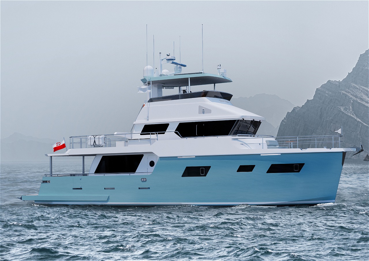
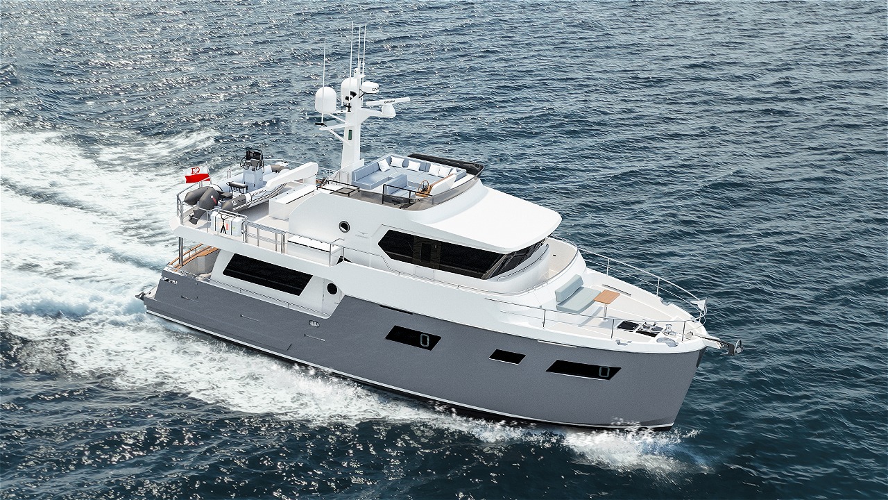
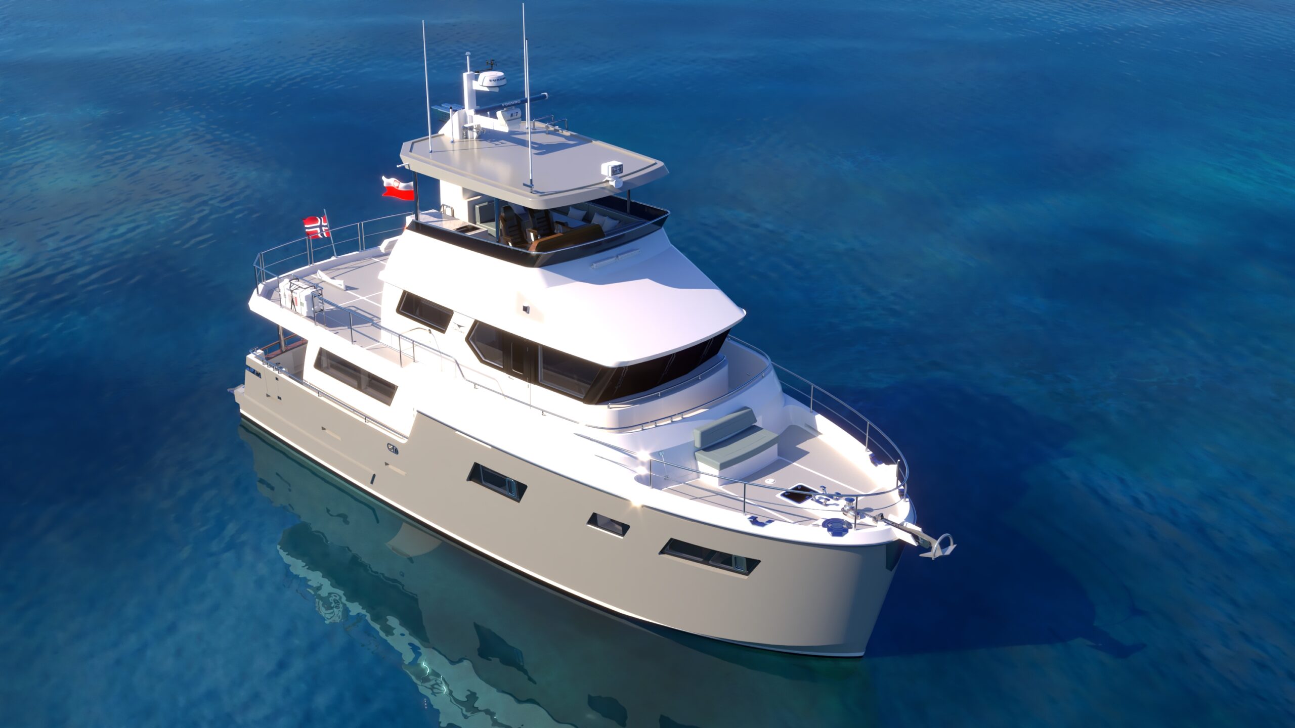
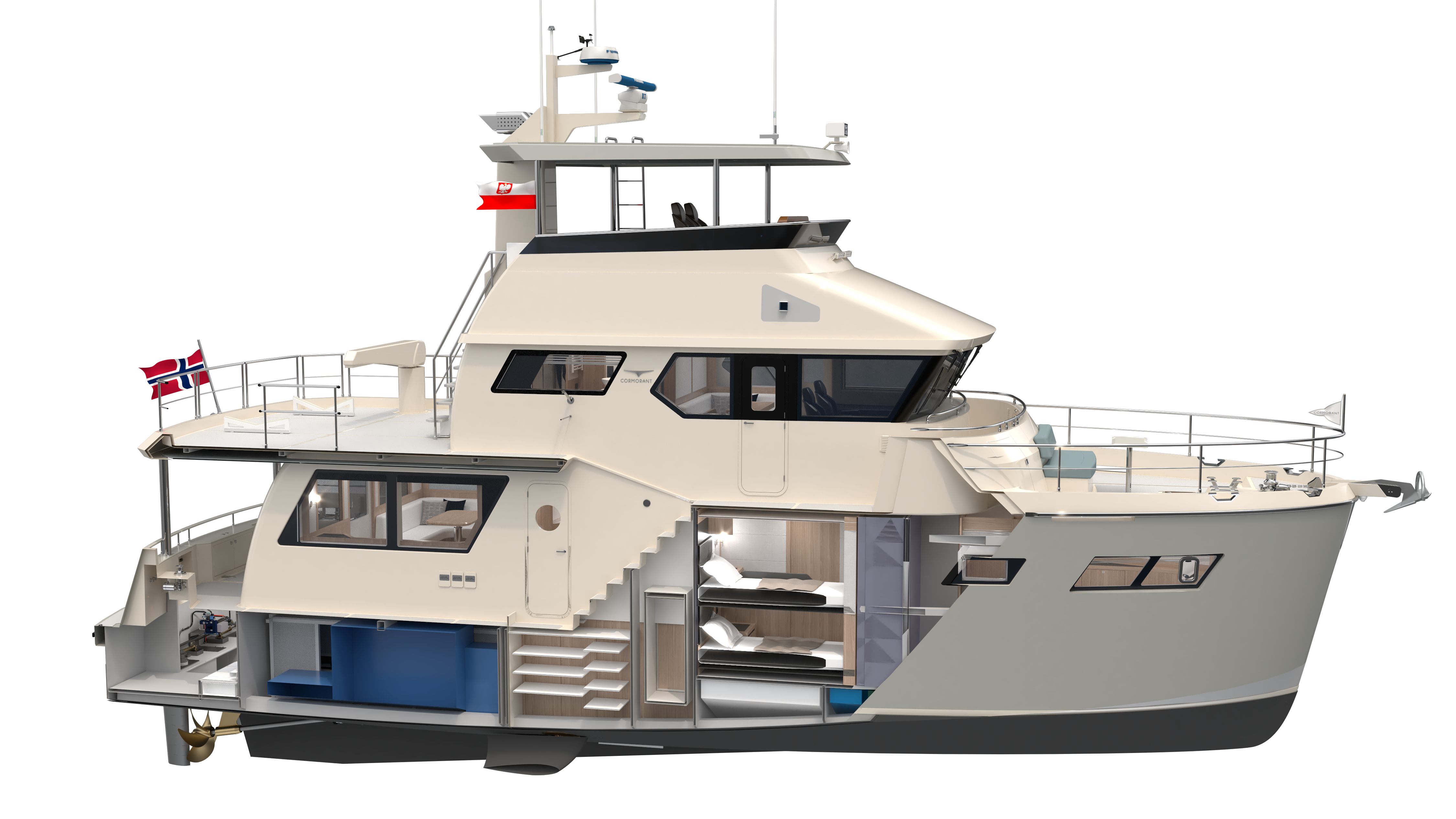
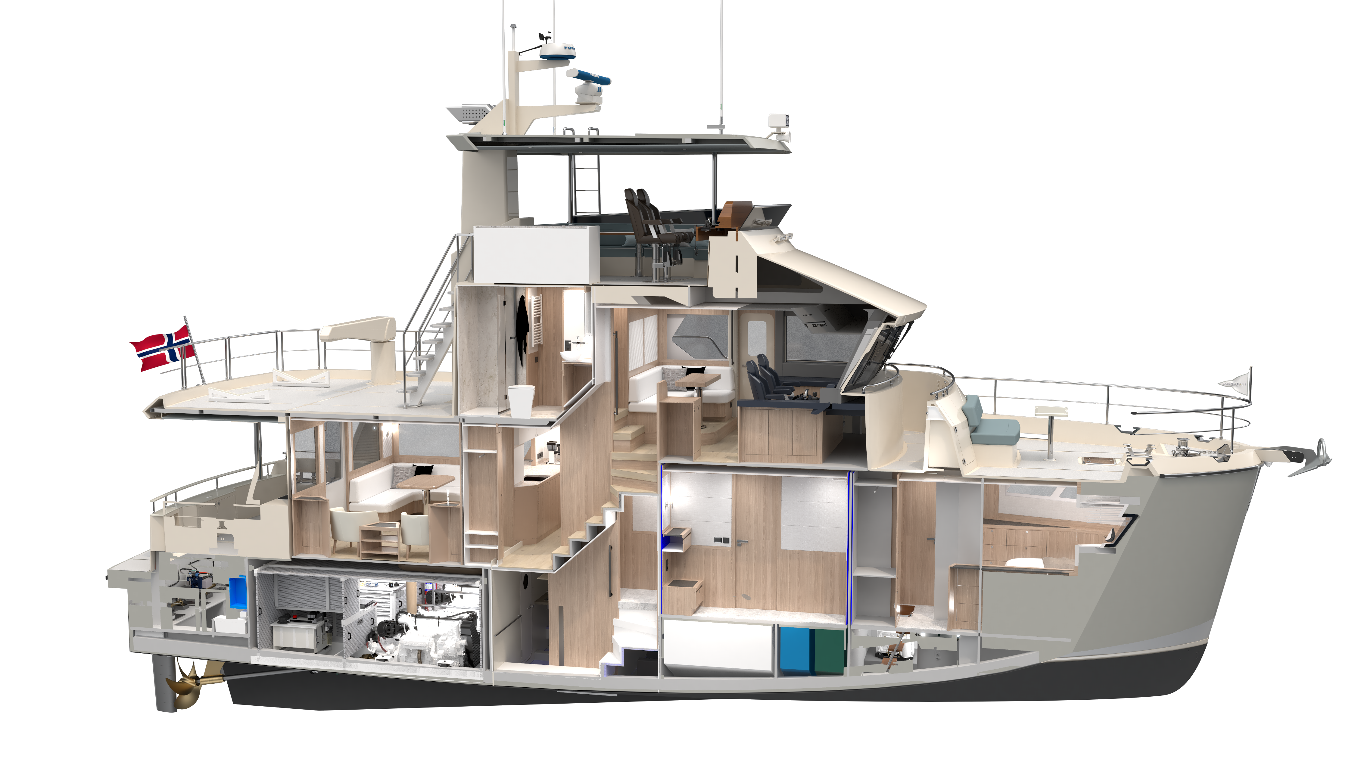
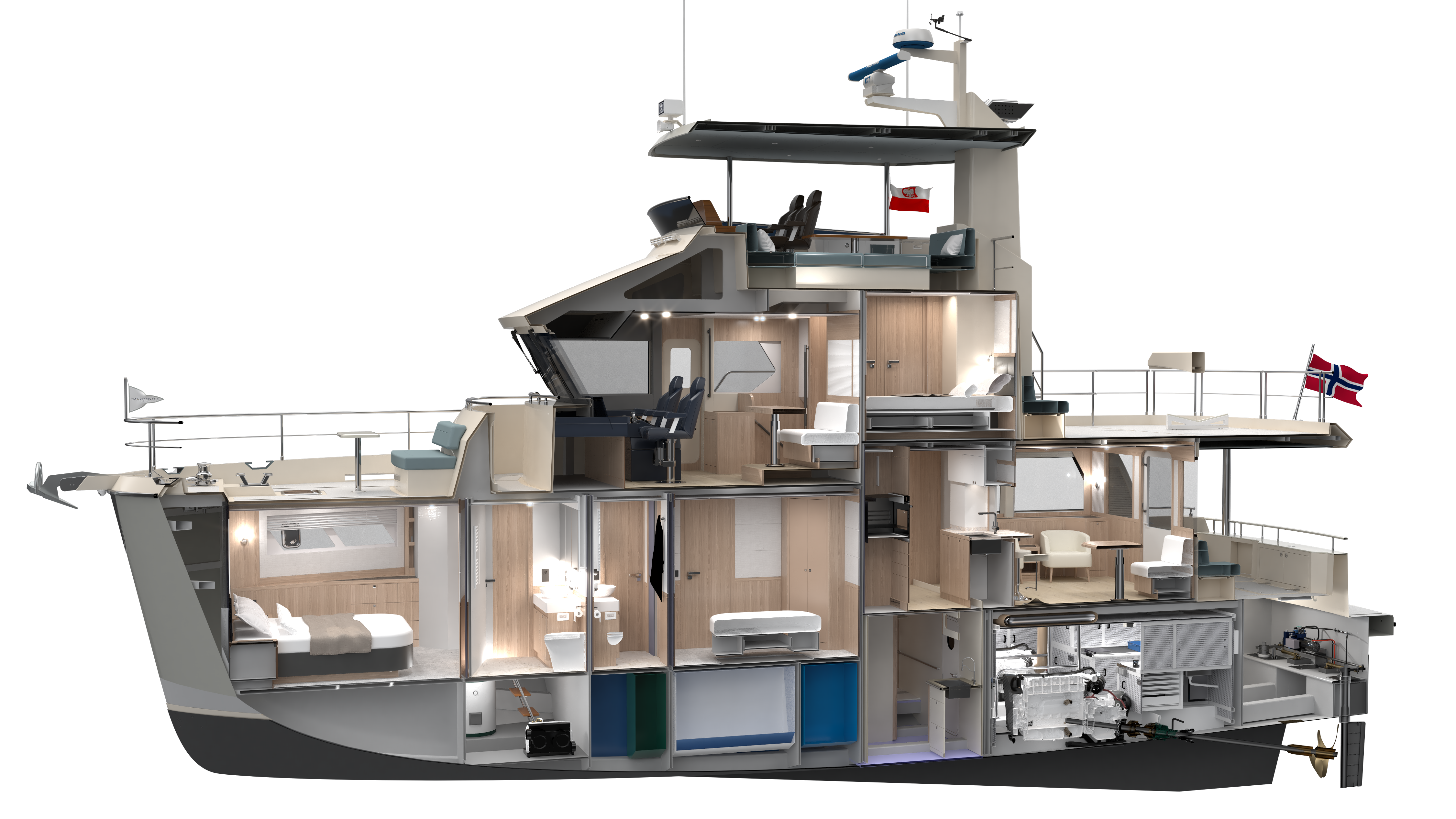
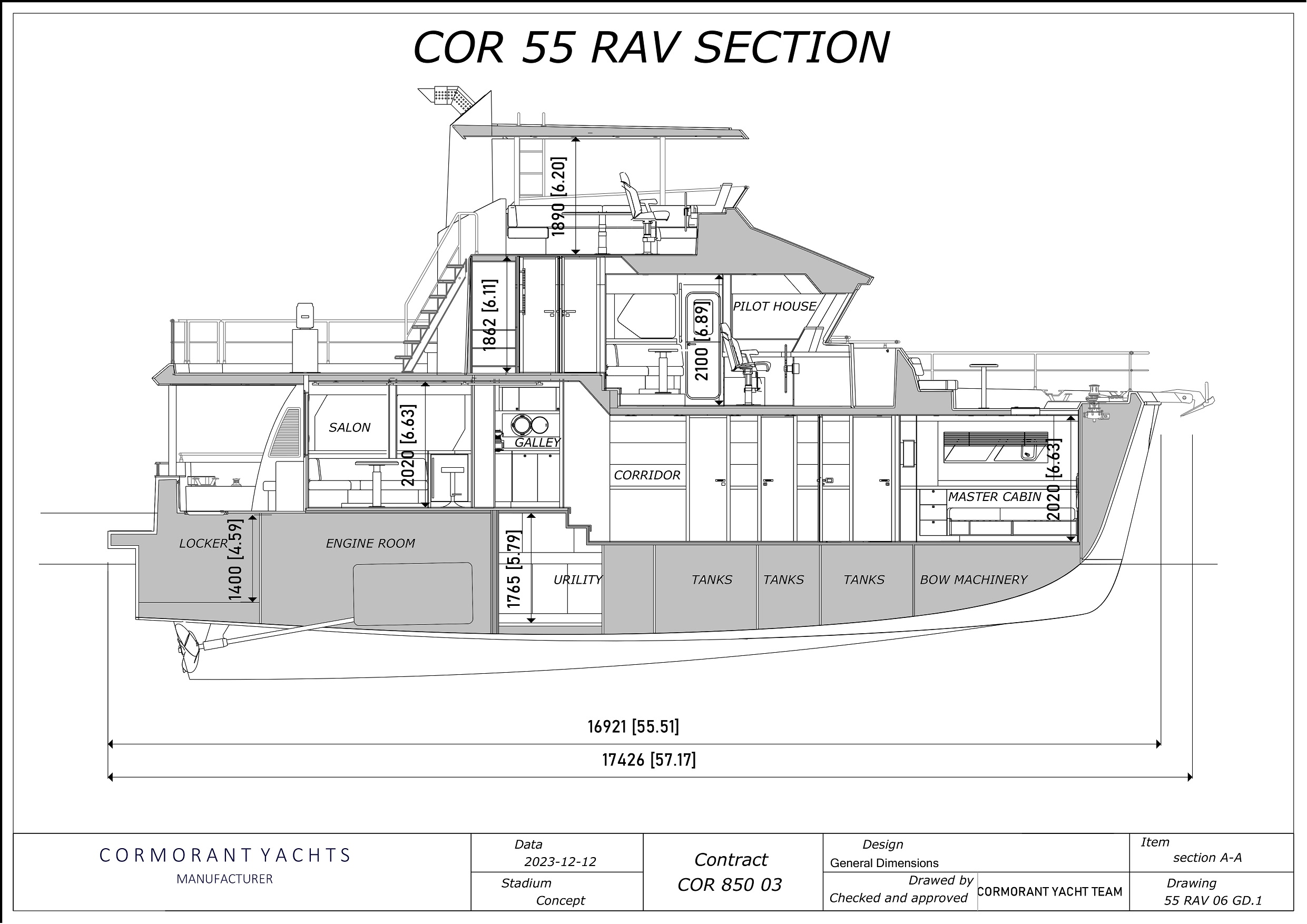
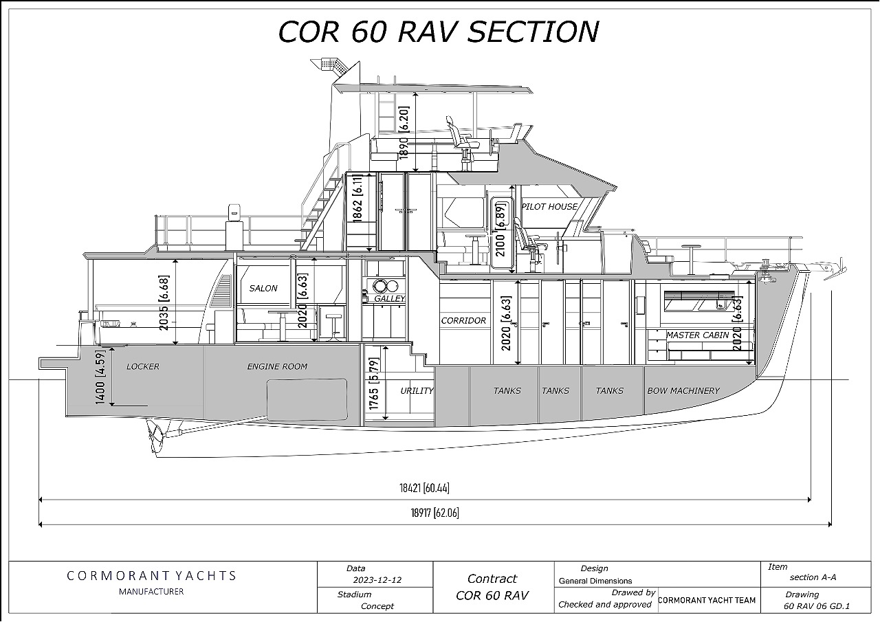
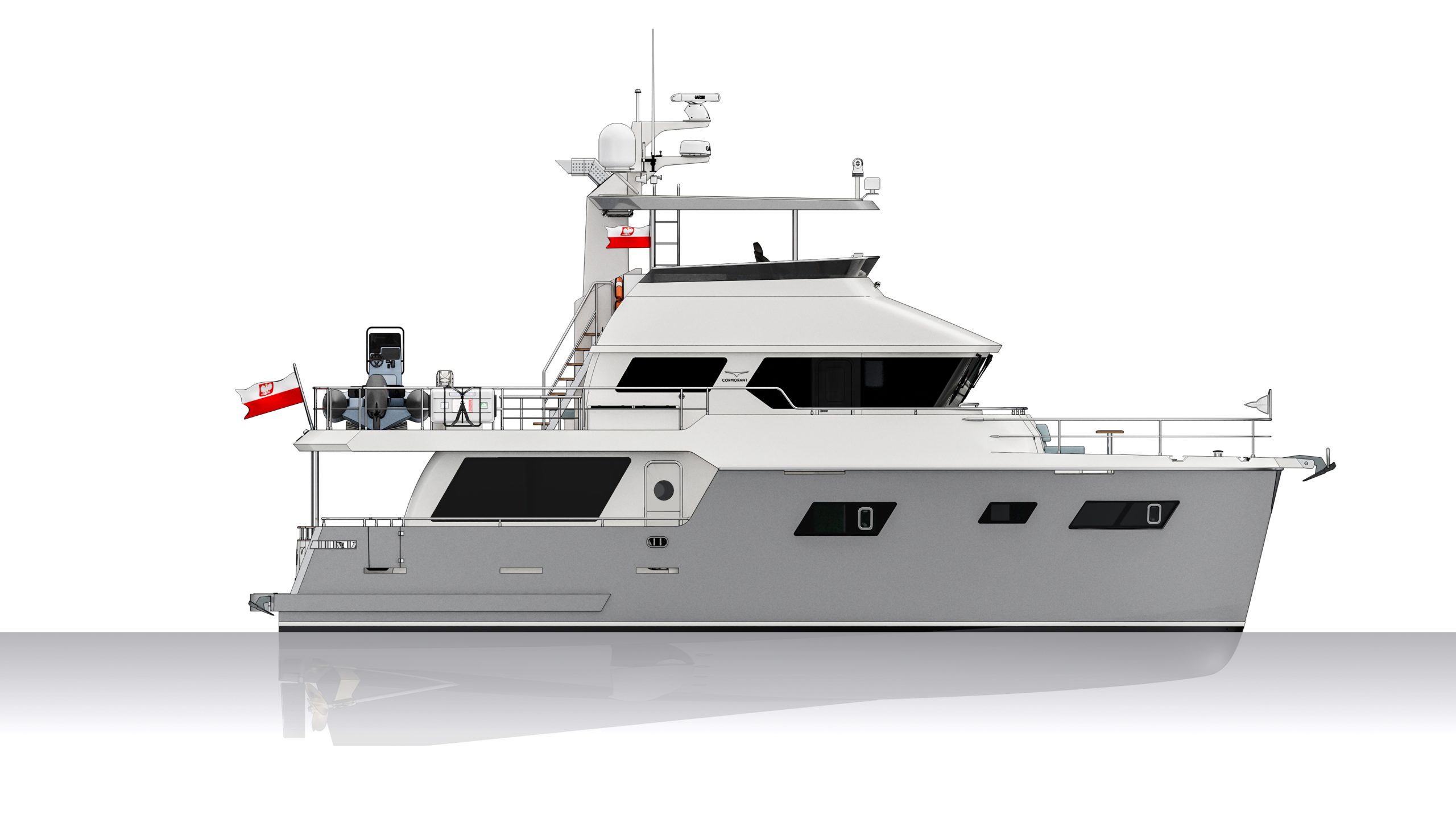
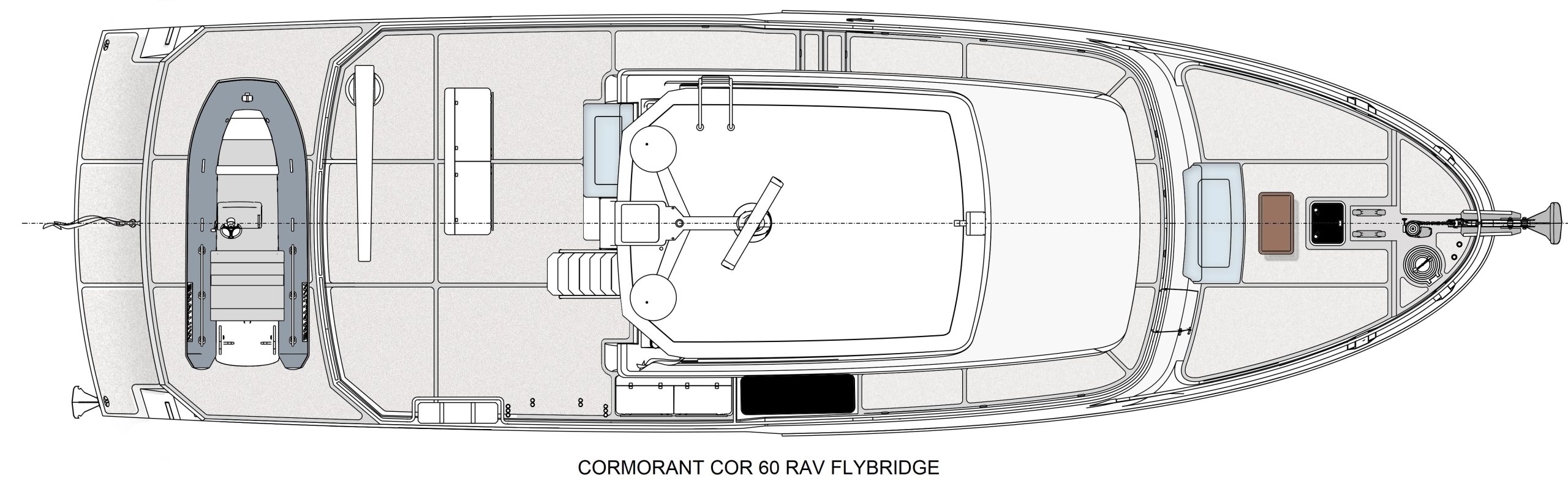
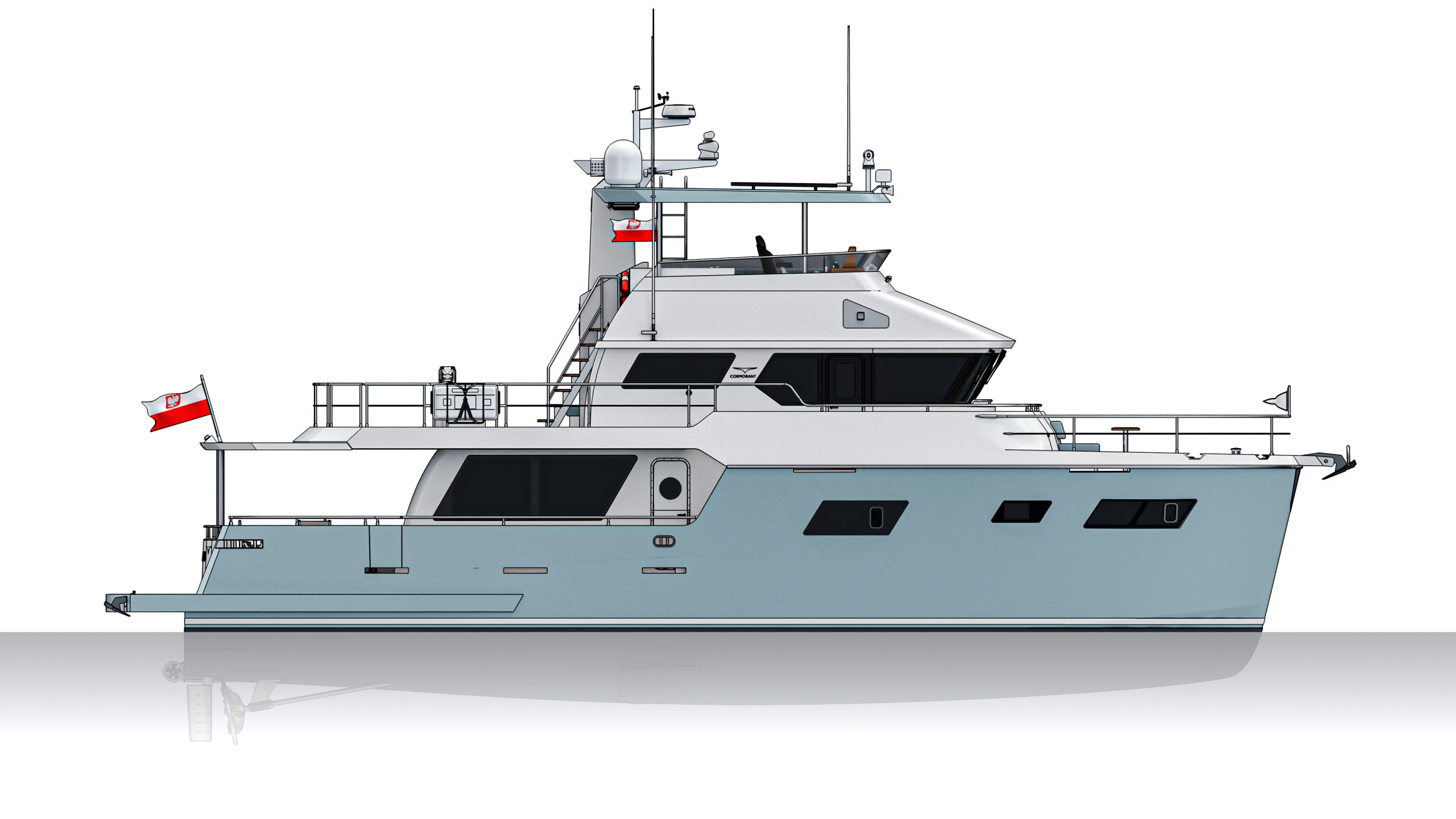
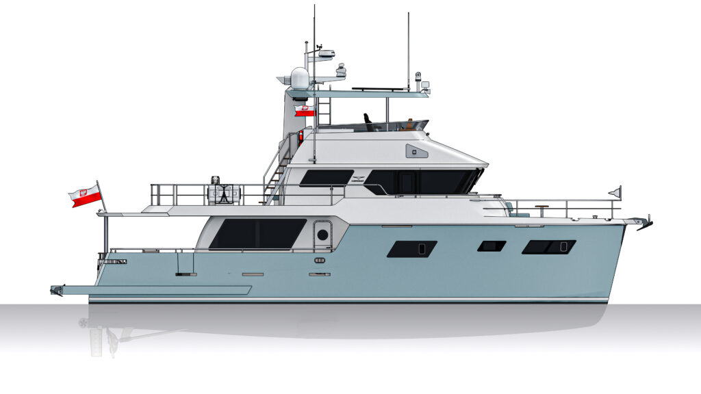
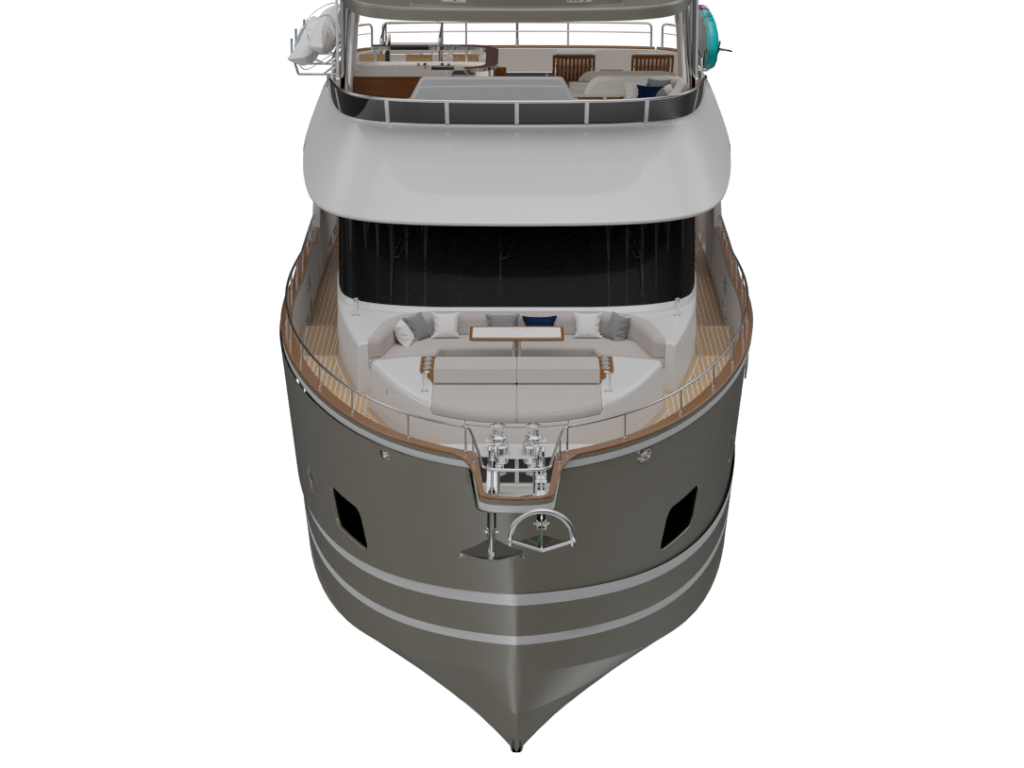
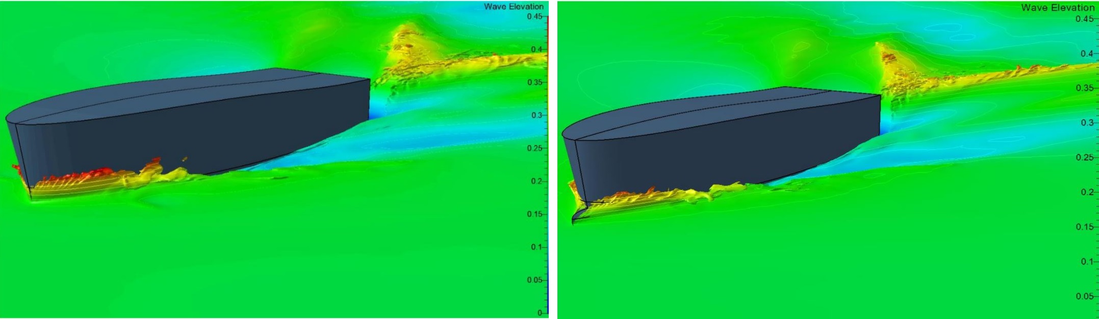
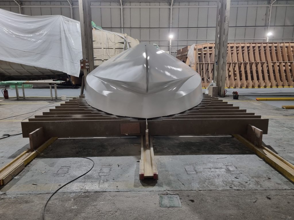
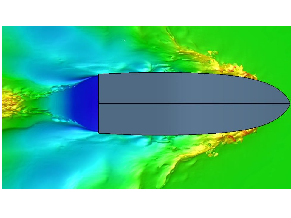
COR55/60 hull and propulsion

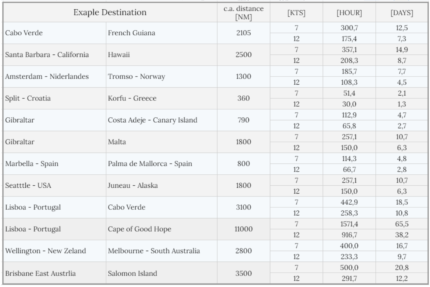
The hull has been designed so that the yacht is very effective in the range of 7-10kts.
Changing times and user trends have influenced the design of the hull, which has the ability to move faster. The most common reason is escaping to a port to escape bad weather and limiting time in open waters when traveling, e.g. between islands.
That’s why we give customers the opportunity to choose between several drive systems. The largest of them, 2x400Hp, allows you to achieve 14kts.

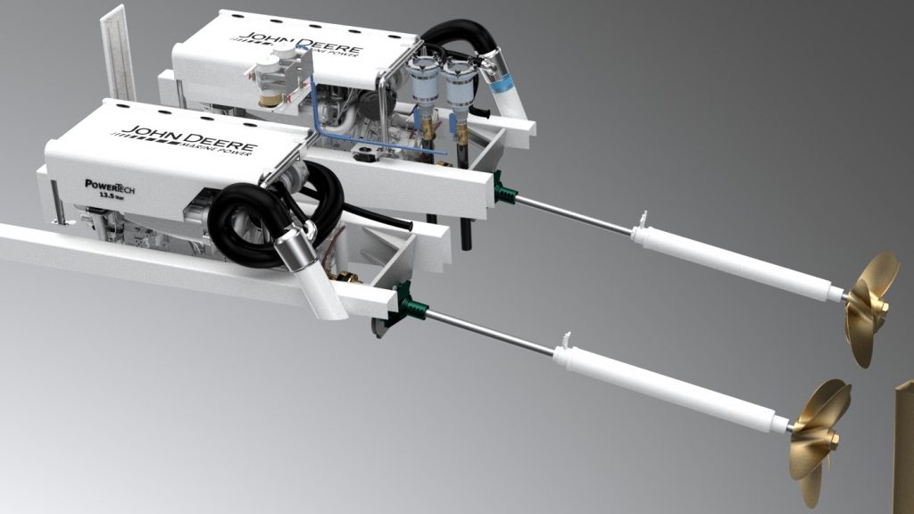
The drive configuration is a typical twin system.
It ensures quiet operation and excellent maneuverability.
This system is fully redundant.

To minimize maintenance needs, we recommend a keel cooling system and a dry exhaust system.
In this case, to reduce smoking when starting a cold engine. The engines are equipped with engine block heaters. This solution additionally reduces the wear of an underheated engine.

It is possible to order a yacht with one main engine located centrally and a wing engine with a lower power.
This solution will slightly lower operating costs.

The drive of a yacht sailing around the world must be easy to operate. Consumable parts are easily available and inexpensive. Widely available service and engines known everywhere.
Engines should meet exhaust emission standards around the world.
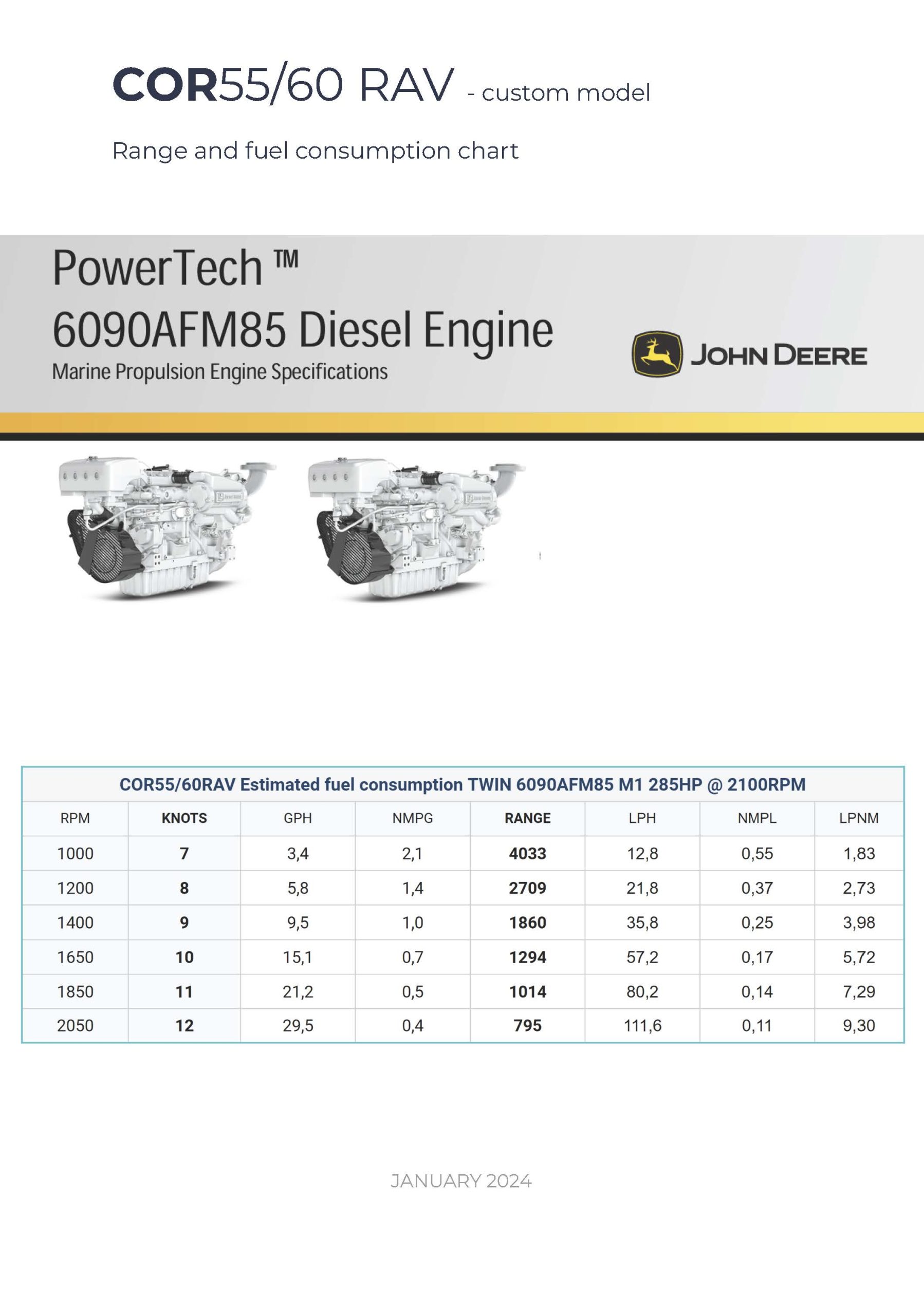
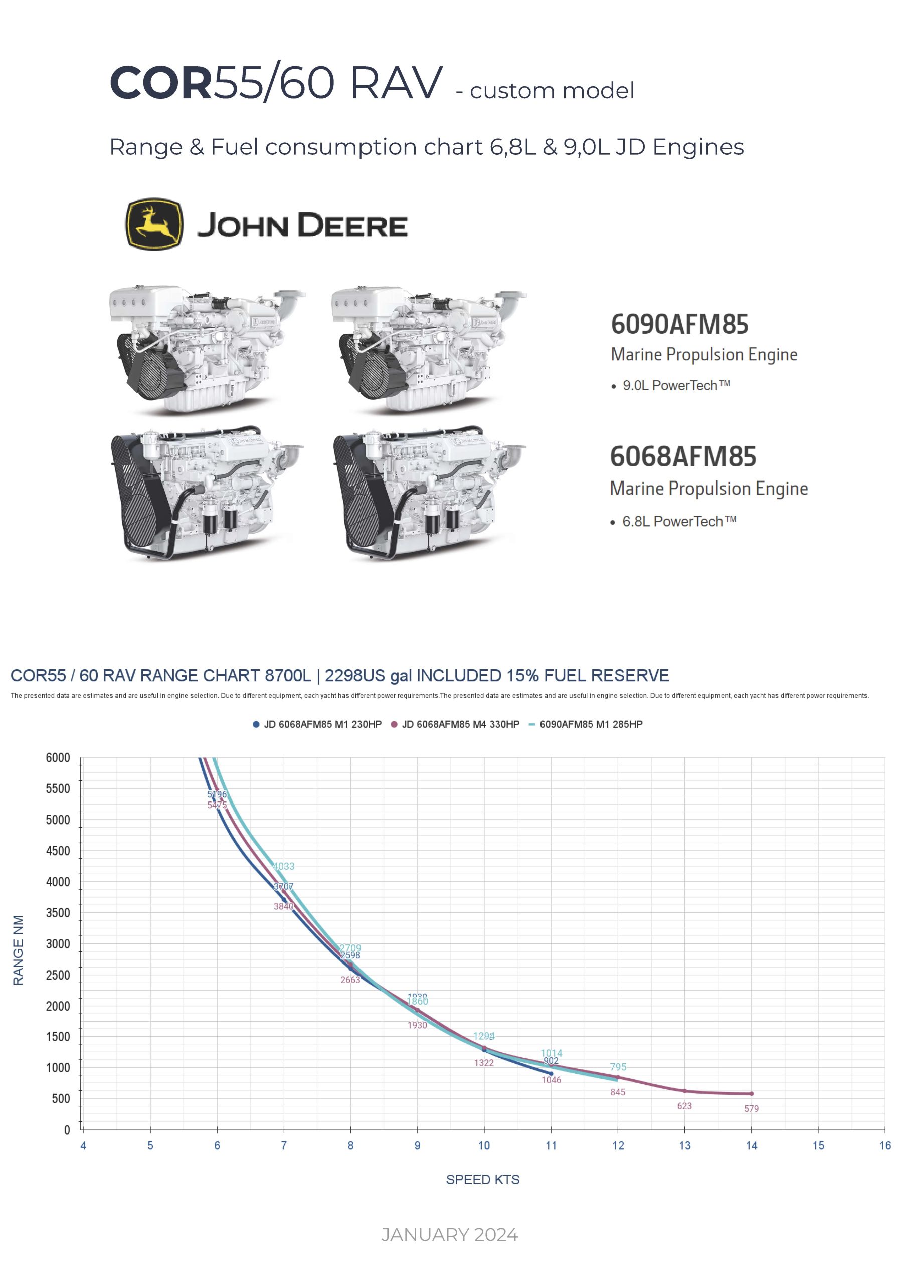
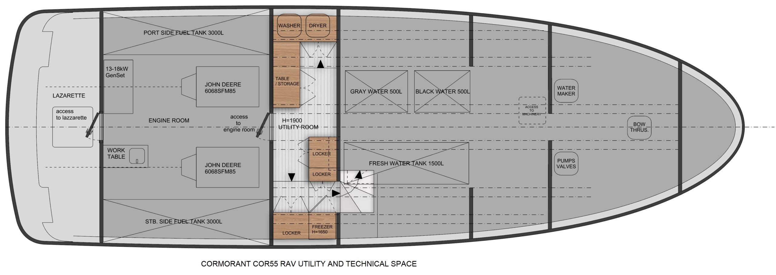
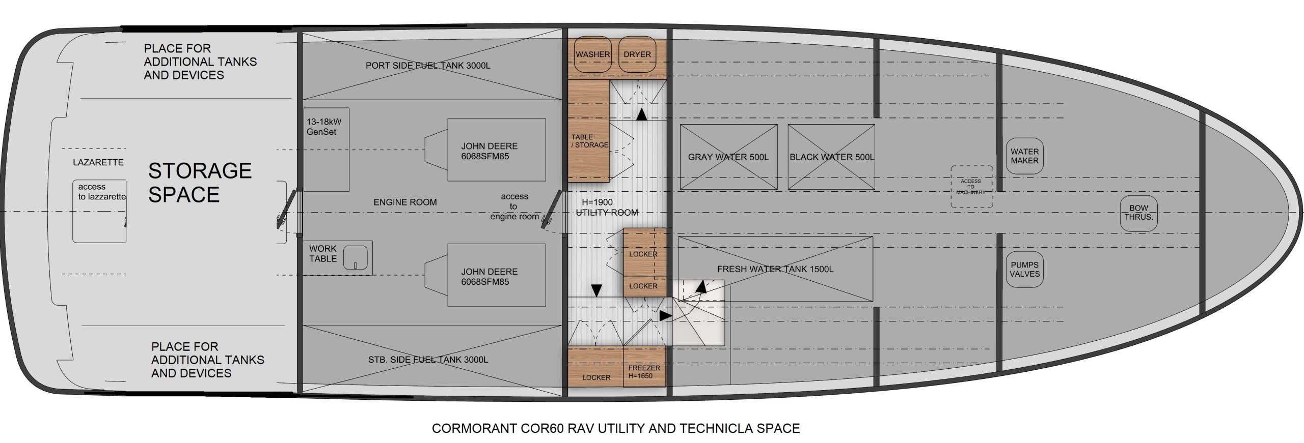
That’s why we chose JOHN DEERE engines and ZF transmissions.
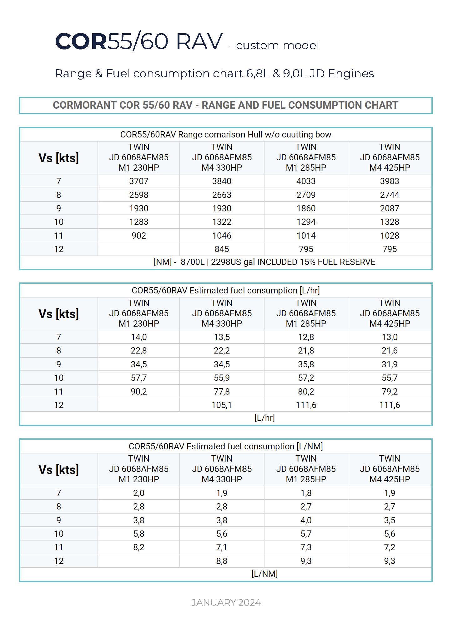
We focus on two engine families
JOHN DEERE 6.8L and JOHN DEERE 9.0.
For installations with dry exhaust and keel cooling, these are models 6068AFM85 & 6090AFM85.

For installations with a wet exhaust system and heat exchanger, specifications with seawater subcooling of the charged air are possible. These will be the 6068SFM85 & 6090SFM85 models.

Each engine can be selected in the rating M1 to M4.
We recommend 230Hp for the 6.8L engine and 285Hp for the 9.0L engine. This will allow for greater system efficiency at speeds of 7-10kts.

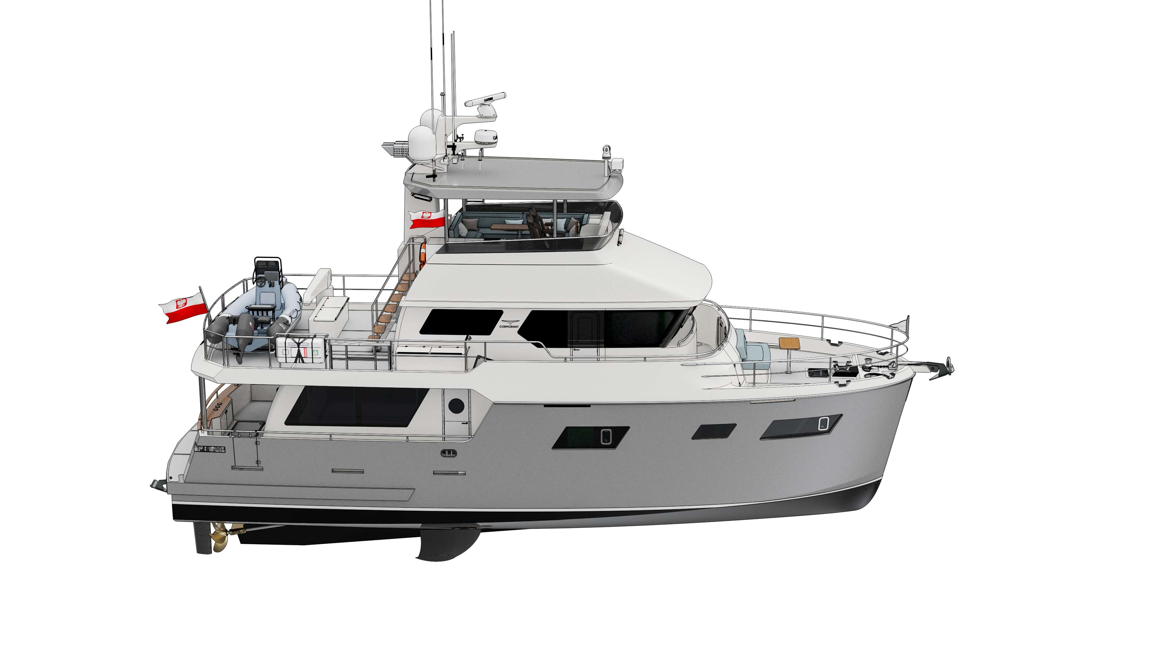
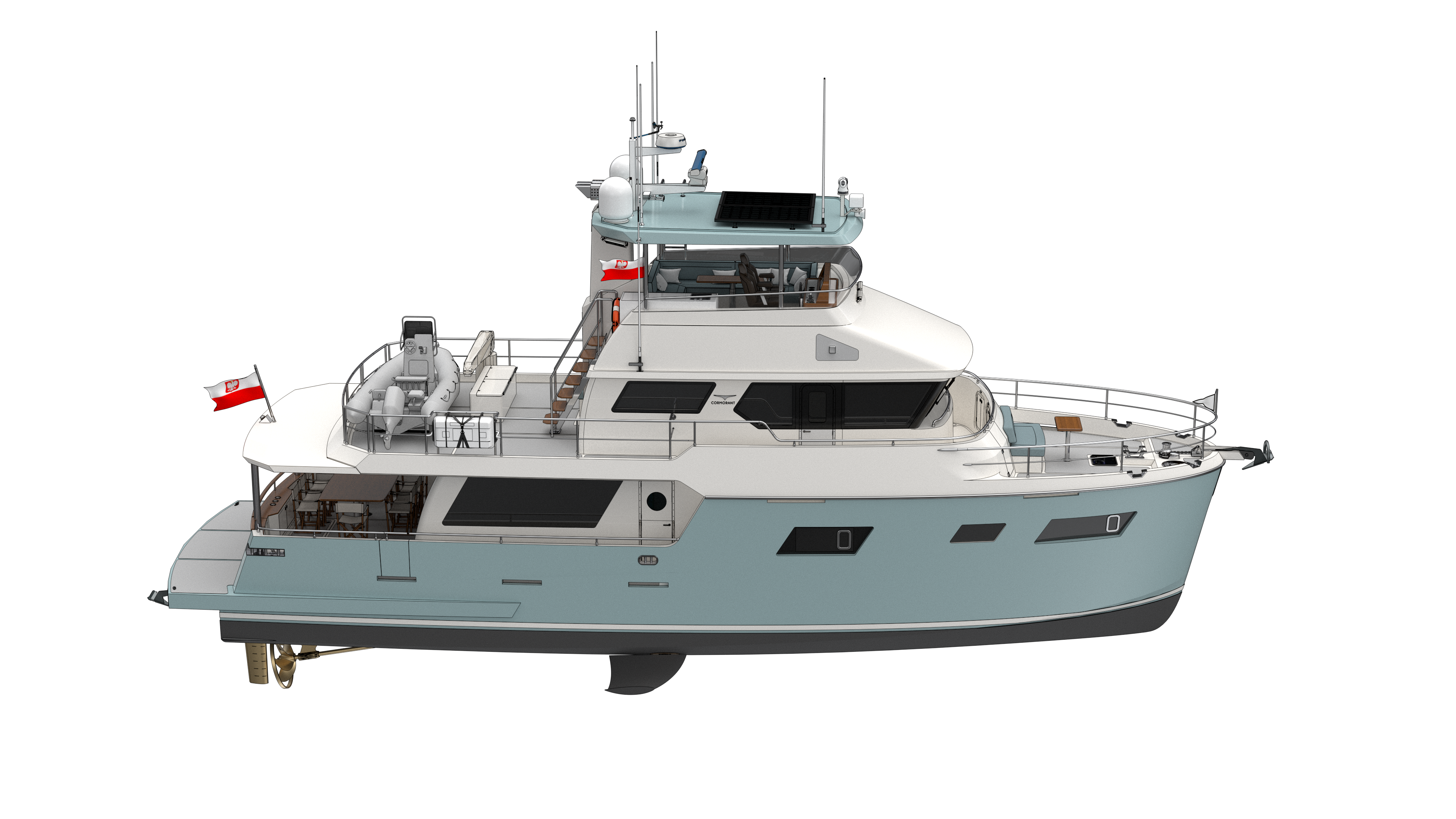
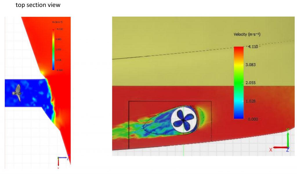
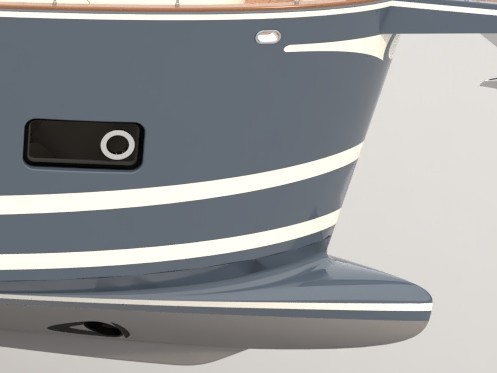
The shaft line is angular with an inclination of 8°-10° and a four bladed propeller with a diameter of 40″
ZF 85A series gears, gear ratio i=2.5
propeller rotation speed at 7kts.
6068AFM85 M1 230HP = 480RPM
6090AFM85 M1 285HP = 400RPM

ZF 301-1A series gears, gear ratio i=2.9
propeller rotation speed at 7kts.
6068AFM85 M1 230HP = 413RPM
6090AFM85 M1 285HP = 344RPM